Double wall chimneys ART-D
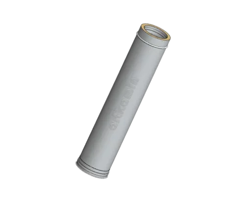
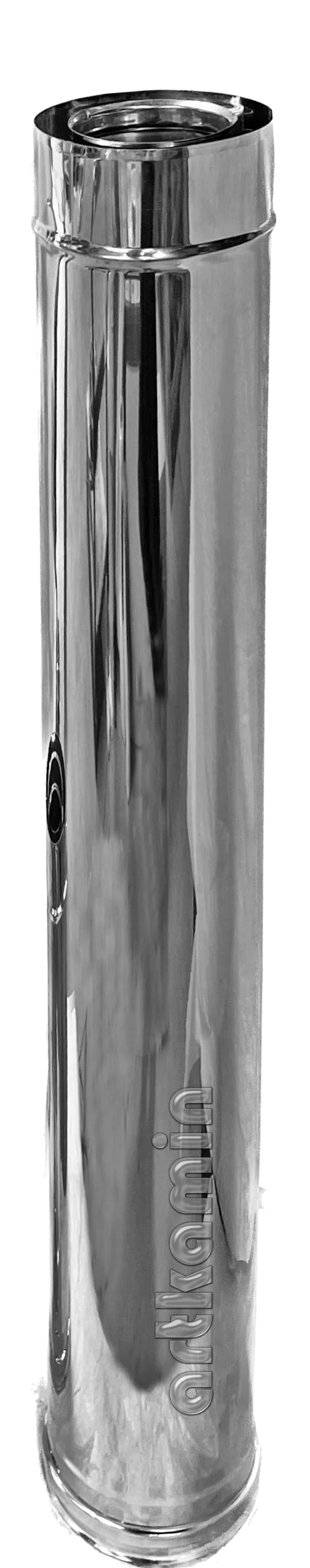
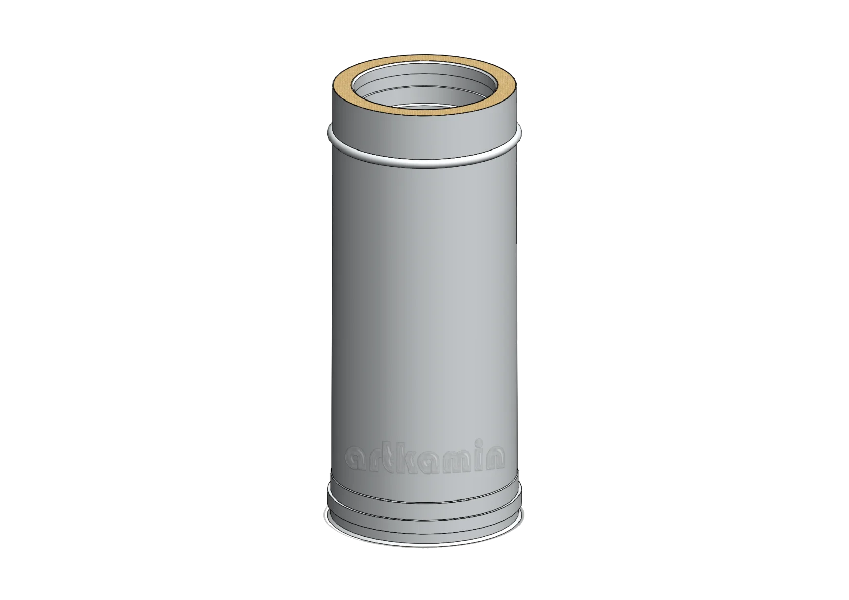
Double wall stainless steel chimney 1m INOX AISI 304L
ΚΩΔΙΚΟΣ ΠΡΟΪΟΝΤΟΣ: ΚΙΙ100
Περιγραφή
Double-wall chimney 1m with intermediate insulation, made of stainless steel AISI 304 (EN 1.4301) with a thickness of 0.4 mm.
- Inner wall: AISI 304 (EN 1.4301), thickness 0.40 mm
- Insulation: Virgin mineral wool, thickness 140 kg/m³ density, 25mm
- Outer wall: AISI 304 (EN 1.4301), thickness 0.40 mm
Additional details
- ⌀ 80-130
- ⌀ 100-150
- ⌀ 130-180
- ⌀ 150-200
- ⌀ 180-230
- ⌀ 200-250
- ⌀ 300-350
- Material thickness 0.40mm
- ⌀ 350-400
- ⌀ 400-450
- ⌀ 450-500
- ⌀ 550-600
- Πάχος υλικού 0.50mm
ATTENTION!
- The chimney assembly method is unique and must be strictly followed for each product line.
- Minimum distances from combustible materials must always be observed (see Product Labeling).
- Locking bands must be installed on all parts.
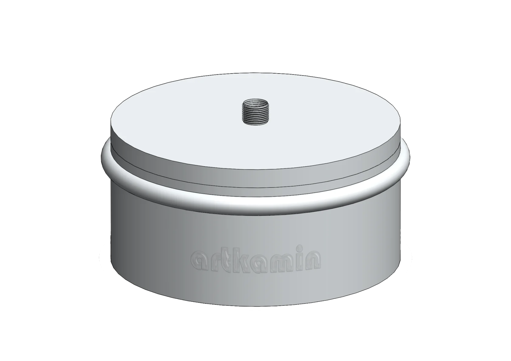
- Re-check the tightness at the terminal end (cap).
- Re-check that wall brackets and triangular wall bases have been installed correctly.
- The installation of the system must comply with applicable laws and regulations.
You can download the assembly instructions for the ART-D double-wall chimneys from here.
Installation of Double-Wall Chimney System – Series ART-D, ART-D PLUS, ART-D EXT PLUS, ART-C
- All chimney parts must be installed so that the inner wall joint faces the direction of the flue gas flow, i.e., downward. This allows condensates to be directed into the branch element (T-piece) and the drainage plug, so they can be removed from the system. The correct installation direction is indicated by an arrow on the product label affixed to each section.
- Measure the appropriate distances, mark the vertical line using a line, and install the wall brackets. Make sure the section joints do not align with the wall brackets.
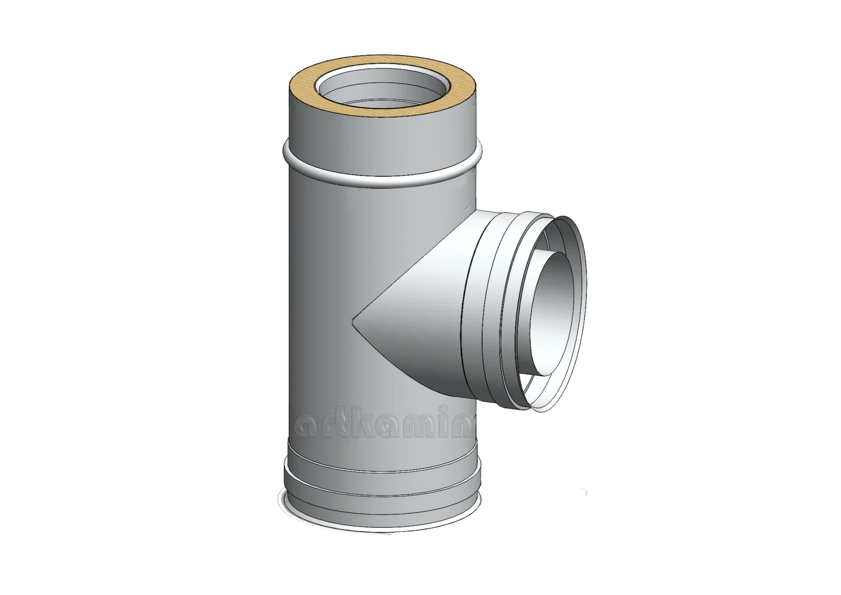
- Install the branch element (T-piece) with the drainage plug. The 90° T-piece at the chimney base is designed and engineered to bear load according to specifications, in combination with wall brackets and wall support bases, as required during installation.
- Use only the supplied connection elements to connect the flue pipe to the heating appliance.
- The silicone gasket must be placed in the specially designed part at the female end of the inner diameter.
- The wall support base is designed to support the weight of the system. The maximum distance between the wall support bases must not exceed 8 meters.
- Continue installing the chimney section by section, up to the terminal cap.
- Install locking bands on all sections.